
Pedestals in Construction: Types, Uses & Design
What a pedestal means in construction
A pedestal is a raised support or base that transfers a load to a larger supporting element or provides a stable, elevated platform for equipment or a finish. The word describes several different products and details. A structural pedestal may support a column or concentrated load; an equipment pedestal can raise a pump, unit, or machine above a slab; an architectural plinth can create a visual base; and an adjustable paving pedestal can support exterior pavers above a waterproofed surface. Those uses are not interchangeable. Before selecting a detail, identify the load, material, location, exposure, and intended role. The drawings and product instructions should define the support system.
Structural pedestals and load transfer
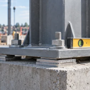
A structural pedestal transfers force from a column, post, wall, or piece of equipment to the element beneath it. Its design may account for bearing area, reinforcement, anchorage, eccentricity, shear, and the condition of the supporting slab or footing. The pedestal is not merely a short block that can be sized by appearance. Concentrated loads require an appropriate load path into the foundation or structure. A contractor should not change its dimensions, reinforcement, or anchor layout in the field without design approval. The engineer’s details govern the concrete strength, reinforcement, connection, cover, and installation sequence. If a supporting surface is damaged or out of tolerance, obtain direction before placing the supported equipment.
Equipment bases and housekeeping pads
Equipment bases and housekeeping pads often elevate machinery to provide a cleaner installation, protect against routine water on a floor, create a level mounting surface, or allow access for maintenance. The required height and footprint depend on equipment and project conditions. Confirm the weight and operating loads, vibration criteria, anchor locations, service clearances, conduit or pipe entries, and whether isolation pads are required. A pad should not obstruct drains, door swings, accessible routes, or adjacent equipment. The equipment supplier’s installation requirements and mechanical or structural drawings should be coordinated before concrete is placed. An apparently small adjustment in pad height can affect pipe slopes, shaft alignment, duct connections, and service access.
Architectural plinths and decorative bases
An architectural pedestal or plinth may visually lift a column, sculpture, display, or feature above a floor. It can be stone, concrete, wood, metal, masonry, or a manufactured finish. Even a nonstructural plinth needs a stable substrate, secure attachment, a finish that suits its exposure, and details at its perimeter. If it is located in a public area, review its edges and projections for trip, impact, or accessibility concerns. The finish should not conceal a moisture-sensitive connection or block access panels. The architect should show the profile, dimensions, material, and how the base meets the floor. Decorative scale may be adjusted, but the support function and clearances must remain intact.
Adjustable pedestals below raised pavers
Adjustable pedestals are also used to support pavers or deck units over a roof terrace, balcony, or other waterproofed surface. They can create a level walking plane above the membrane and allow drainage below the pavers. The assembly depends on the roof design, paver thickness, wind exposure, loads, edge restraint, and membrane protection. Confirm compatibility among the pedestal, paver, drainage layer, and waterproofing system. Keep required outlets clear and preserve access to drains and service points. Do not assume that a pedestal system can compensate for any slope or substrate condition. The designer and manufacturer should approve the specified build-up, including perimeter conditions, uplift restraint, and protection of the waterproofing.
Materials, anchorage, and corrosion protection
Pedestals may be cast in place, precast, fabricated from steel, built from masonry, or made from adjustable polymers. Select a material appropriate to the load, fire requirements, wet or exterior exposure, chemical environment, and maintenance plan. Metal anchors and base plates need suitable corrosion protection where they may be exposed to moisture. In concrete, anchor embedment, edge distance, reinforcement conflicts, and installation tolerance must match the approved detail. For adjustable products, verify the rated capacity and stability for the exact height used. Materials that look similar can have different allowable loads, movement limits, and temperature performance. Use project-approved product data rather than estimating capacity from dimensions alone.
Set-out and installation checks
Before installation, check centerlines, top elevation, footprint, support capacity, and clearances against coordinated drawings. Confirm anchor bolts or inserts are located before concrete placement and protected from displacement. For cast-in-place pedestals, verify formwork, reinforcement, concrete placement, and curing requirements. For equipment bases, confirm the final mounting surface is level within the equipment tolerance. For paving pedestals, check membrane protection, drainage direction, joint layout, and perimeter restraint. Photograph concealed components where required by the project. If the pedestal is out of position, do not elongate slots or drill new holes without verifying that the change will not affect structural capacity or waterproofing.
Common pedestal problems and prevention
Common issues include inadequate bearing, incorrect height, mislocated anchors, blocked drainage, vibration, cracking, corrosion, and poor access for maintenance. These failures often begin with a missing coordination step: equipment dimensions were not final, services were routed after the pad was formed, or the waterproofing detail was not coordinated with the pedestal layout. Prevent them by checking approved submittals before work, confirming field dimensions, and resolving conflicts early. Monitor cracks or movement rather than covering them with a finish. If water collects around a base, trace the source and check slope, drain locations, and the intended water-management detail. A repair should address the cause as well as the visible symptom.
Inspection, maintenance, and documentation
Inspection should focus on the pedestal’s actual function. Verify that structural supports match the engineered detail, that anchors and connections are secure, and that equipment remains aligned. At a roof terrace, confirm pavers are stable, drainage outlets remain open, and access to the membrane is possible. Record product identification, installation height, and maintenance information for adjustable systems. Follow the equipment manufacturer’s recommendations for checking vibration and fastening. In a facility, keep a clear route to disconnects and service points. Maintenance staff benefit from drawings that show what lies beneath removable pavers or a decorative cover, reducing the chance of accidental damage during later repairs.
Frequently asked questions
Is a pedestal always structural? No. It may be a load-bearing support, equipment base, architectural feature, or adjustable paver support. Identify its function first.
Can a pedestal be moved to avoid a pipe? Only after the structural, mechanical, and architectural impacts are reviewed and approved.
Do roof paver pedestals replace waterproofing? No. They sit above a separate waterproofing assembly and must be compatible with its protection and drainage design.
How high should an equipment pad be? The project drawings and equipment requirements control; do not choose a height from a generic rule.
A practical coordination checklist
For each pedestal, note its purpose, supported load, material, footprint, elevation, anchors, substrate, exposure, service access, and interaction with drainage or adjacent finishes. Confirm these details with the responsible designer and product supplier before ordering or forming. Verify field conditions before installation and inspect concealed work before it is covered. The term “pedestal” covers several systems, so a strong detail states what it supports and how the load or water moves through the assembly. That clarity helps prevent the common mistake of treating a functional support as a simple decorative block.
Pedestal height and adjacent trades
Height affects more than appearance. A raised base may change pipe elevations, conduit routes, equipment connections, access to filters, and the relationship to adjacent floors. Confirm the finished floor thickness before setting the pedestal elevation. If the surrounding surface slopes to a drain, the detail must account for the slope without leaving the supported equipment out of level. At a roof, the pedestal height also influences wind exposure, edge restraint, and the step at door thresholds. Coordinate these conditions on a section detail rather than relying on a dimension taken from an unfinished slab. Verify the final elevation after all finish layers are known.
When field conditions differ
Existing buildings often have uneven slabs, unknown reinforcement, buried services, or limited access. Before drilling anchors or adding a concentrated support, locate embedded utilities and confirm the substrate can accept the connection. If the actual surface differs from the drawings, document the condition with measurements and photographs and obtain a revised detail. Do not shim with loose scraps, cut reinforcement, or move a support to avoid a conflict without approval. A small change can alter load distribution or create a maintenance problem. Keep the approved response with the closeout records so later crews know what was installed and why.
What a useful submittal should show
A pedestal submittal should identify the model or design, dimensions, material, rated capacity where applicable, anchorage, substrate, installation method, and limitations. For adjustable paver supports, show the intended height range, head or pad type, protection layer, joint layout, edge condition, and drain access. For equipment bases, coordinate the equipment footprint, anchor pattern, vibration isolation, service clearances, and connected services. A product sheet alone may not show the job-specific layout. Mark up the drawing with actual locations and dimensions so the design team can review whether the system fits the building conditions.


Leave a Reply
Want to join the discussion?Feel free to contribute!