
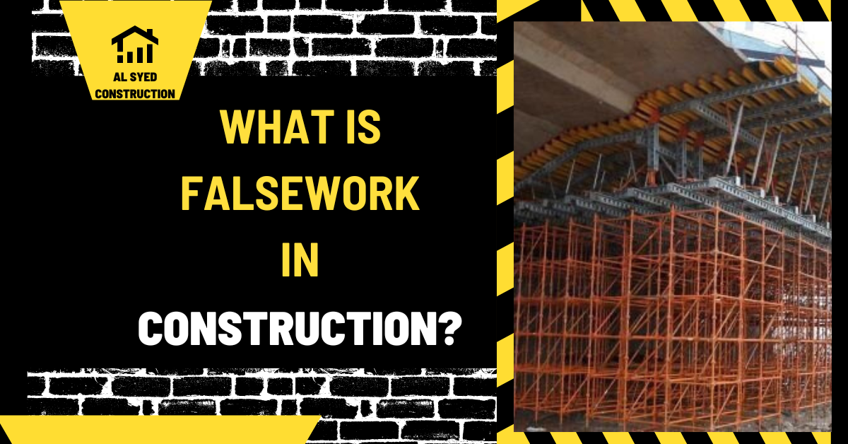
Falsework in Construction: Purpose and Safety
Falsework is a temporary support system used to hold a structure, formwork, or construction material in position until the permanent work can safely carry its own loads. It is common in cast-in-place concrete, bridge work, arches, and other operations where a partially completed element cannot yet stand independently. Because falsework carries changing loads during construction, its design, installation, inspection, use, and removal must be planned as part of the work sequence.
What falsework supports
Falsework may support formwork that shapes fresh concrete, reinforcing steel, workers, equipment, and materials placed during the pour. It may also support a structural element while it is being assembled, connected, or brought to its final position. The exact arrangement depends on the geometry, construction method, ground conditions, access, and stage of work. A temporary support plan should identify the complete load path from the supported work through the falsework and into a stable base.
Falsework is temporary, but that does not make it simple or incidental. Fresh concrete is heavy, and its placement sequence can cause the load to change across the structure. Workers, pumps, buggies, stored materials, wind, vibration, and equipment can also affect a temporary system. An apparently stable support can fail if a base settles, a brace is missing, a connection is not engaged, or the crew changes the pour sequence without authorization.
Falsework, formwork, shoring, and scaffolding
These terms are related but describe different functions. Formwork is the mold or surface that gives fresh concrete its shape. Falsework supports the formwork or construction assembly while the permanent structure is incomplete. Shoring broadly describes temporary supports used to carry loads or stabilize work, and it may be one part of a falsework system. Scaffolding primarily provides a temporary working platform and access, though a particular project system may have additional engineered functions.
In conversation, crews may use some of these terms loosely. For drawings, contracts, and safety planning, identify what the equipment is actually intended to do. A scaffold should not be assumed to support formwork, and a form panel should not be assumed to carry a load without the designed supports and connections. The project documents and responsible designer should establish the system’s role.
| Term | Main function | Key planning question |
|---|---|---|
| Formwork | Contains and shapes fresh concrete | How is the form supported and kept in position? |
| Falsework | Temporarily carries work until the permanent structure can support it | What is the complete load path and when may support be released? |
| Shoring | Provides temporary support or stabilization | What loads and conditions is the shore system designed for? |
| Scaffolding | Provides access and a working platform | Who may use it, and what platform and access rules apply? |
Where falsework is commonly used
For a concrete floor or beam, falsework can hold forms and reinforcing steel while concrete is placed and gains strength. Bridge falsework may support a deck, arch, or other element over a roadway, waterway, or valley. A tunnel or special structure may require temporary support while successive sections are constructed. In each case, the arrangement must reflect the shape of the permanent work and the sequence by which it becomes stable.
Falsework can also appear during modular and prefabricated construction. Temporary supports may hold a module or assembly during a planned setting and connection sequence. The responsible team must distinguish those temporary supports from the permanent bearing and connection system. For background on how modules are placed and connected as part of a building project, see the guide to modular building installation. The installation plan and engineering documents should state which temporary measures apply to the specific project.
Plan the temporary system before work begins
Falsework planning starts with the permanent design and the construction sequence. The design and field teams should identify what will be supported, the stages at which loads are applied, the expected concrete placement or assembly sequence, and the point at which the completed work can carry itself. The plan should also address the supporting surface, adjacent construction, weather exposure, site access, and any traffic or public protection that the work requires.
A qualified designer should develop or review the falsework design when required by the project and applicable rules. The design documents should communicate member sizes and locations, bracing, connections, bearing conditions, foundations or sole plates, allowable adjustments, and the intended sequence. Field personnel need a usable layout, not just a generic product brochure. Any project-specific load assumptions or calculations belong with the responsible design professional; crews should not improvise capacities from appearance or past experience.
Coordination matters when different companies supply forms, shores, rebar, concrete placement, cranes, and inspection. The team should assign who prepares the temporary works plan, who checks ground and bearing conditions, who verifies installation, who controls access, and who authorizes a change or release. If the falsework crosses a road, work area, or property boundary, the project may also need permits and protection plans. Those arrangements should be resolved before the system blocks access or creates a hazard.
Loads and construction sequence
The system must be considered as a whole. Its design basis may include the weight of forms and fresh concrete, reinforcing steel, workers, equipment, stored materials, and the effects of placing operations. Conditions such as wind, vibration, uneven loading, impact, and support settlement may be relevant. Which conditions govern is project-specific. A change to the sequence can change how load is distributed, so the planned method should be shared with the people placing concrete and operating equipment.
Consider a beam pour as an example. The forms and supports are erected, inspected, and accepted before placement. Concrete is then placed according to the approved sequence while the team watches for movement, distress, leakage, or other signs that require work to stop. After placement, the concrete remains supported until the responsible professional confirms that the structure has reached the required condition for the next step. The crew then follows the planned release sequence and removes the temporary system without damaging the permanent work or destabilizing adjacent areas.
Do not use an assumed number of days as a universal release rule. Strength gain depends on the concrete, mix, temperature, curing, member, and design. The release decision should follow project requirements and the responsible professional’s direction. Where reshoring or backshoring is specified, its location and sequence should be coordinated with the floors or members above and below.
Installation checks and inspection
Before use, compare the erected system with the approved layout. Check that members, bases, connections, braces, and bearing points are in the specified locations and are secure. Verify that the supporting ground or structure is suitable for the planned load and that water, excavation, or nearby work has not undermined it. Confirm that access routes, exclusion areas, fall protection, and emergency arrangements are in place for the activity.
Inspection should continue as work proceeds. The team should know who is authorized to stop placement and whom to notify if a shore moves, a connection slips, a support settles, or the form begins to distort. After a significant change in conditions or an event that could affect the system, an appropriate competent person or qualified professional should determine whether it is safe to resume. OSHA requirements and local rules may specify design, inspection, and protection duties for particular concrete operations; the project safety lead should verify the provisions that apply.
Keep records of the approved design, inspection, approved revisions, concrete placement, strength information used for release, and authorization to remove support. These records help the contractor confirm that the planned sequence was followed and provide useful information if questions arise later. Documentation does not replace field inspection, but it helps the team connect design intent to the work actually installed.
Safe removal and release
Removal is a planned construction operation, not simply the reverse of installation. The permanent element must be ready to carry the loads that will transfer to it. The approved release sequence should limit sudden load changes and avoid leaving an unstable portion unsupported. Protect workers from falling components, dropped materials, pinch points, and work beneath the removal area. Keep unauthorized people away and coordinate the work with any operations below or beside the falsework.
Crews should not remove braces, alter shores, or use a different sequence to speed work unless the change is reviewed and authorized through the project process. If reuse is planned, inspect components for damage, deformation, missing parts, and contamination according to the supplier’s instructions and the project quality plan. A component that appears reusable may still be unsuitable for the next configuration; the system’s design and condition should be evaluated rather than assumed.
Common falsework problems to prevent
- Incomplete bracing: A support layout may look vertical but still lack the lateral restraint shown in the design.
- Weak or uneven bearing: Soft, wet, disturbed, or sloping ground can affect the support base.
- Unapproved field changes: Removing a member or shifting a shore can change how loads travel.
- Uncontrolled material storage: Concentrated stockpiles may create a load not included in the planned sequence.
- Premature release: Permanent work may not yet be ready to carry its intended loads.
- Poor coordination: A change in concrete placement, equipment, or site access can conflict with the temporary works plan.
Questions to resolve in a project review
- What exact element, formwork, or assembly does the falsework support?
- Which approved drawings and design documents govern erection and use?
- Who checks the support surface, bearing points, connections, and bracing?
- What placement or assembly sequence is required, and who may authorize a change?
- How will movement, settlement, damage, or adverse weather be handled?
- What inspection records and concrete or material information are required?
- Who confirms the permanent work is ready, and who authorizes falsework removal?
Conclusion
Falsework temporarily supports construction until the permanent work is capable of carrying the required loads. It is distinct from the concrete mold itself and from scaffolding used primarily for access. Safe use depends on a project-specific design, a stable load path, an approved construction sequence, inspection, and authorized release. When the temporary system is included in planning and coordination from the start, contractors can reduce the risk of movement, collapse, damage, and costly rework while carrying out the permanent construction.





Leave a Reply
Want to join the discussion?Feel free to contribute!