
Duct Bank in Construction: Electrical Conduits and Planning
Introduction
In the construction industry, a duct bank is a critical infrastructure component used to protect and consolidate electrical and communication cables. It is a conduit system that provides a secure pathway for these cables, often buried underground, to ensure their safety and accessibility. Understanding the purpose, construction, and benefits of duct banks is essential for engineers, contractors, and project managers involved in the planning and implementation of electrical and communication systems in various construction projects.
Purpose and Function of Duct Banks
Protection of Cables
The primary function of a duct bank is to provide physical protection for electrical and communication cables from external damages, such as impacts, moisture, and chemical corrosion. This protection is crucial for maintaining the integrity and functionality of the cables over time.
Organization and Consolidation
Duct banks also serve to organize and consolidate multiple cables into a single, manageable pathway. This consolidation facilitates easier installation, maintenance, and future upgrades of the cable systems.
Construction of Duct Banks
Materials and Components
Duct banks are typically constructed using rigid conduits made of materials like PVC, fiberglass, or metal. These conduits are assembled into a bank and encased in concrete, providing additional protection and structural stability.
Installation Process
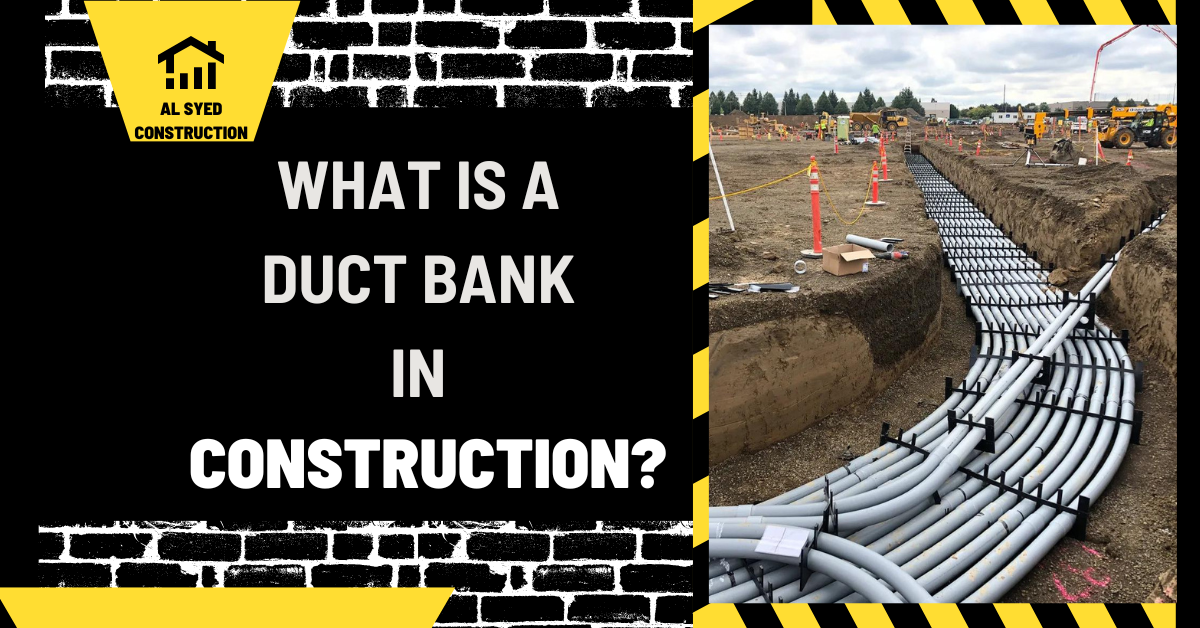
The installation of a duct bank involves excavating a trench, laying out the conduits in the desired configuration, and then pouring concrete to encase the conduits. Once the concrete has cured, the cables can be pulled through the conduits, and the trench is backfilled.
Benefits of Using Duct Banks
Enhanced Safety
By encasing cables in a concrete-protected conduit system, duct banks significantly reduce the risk of electrical accidents and fires, enhancing the overall safety of the construction project and its occupants.
Improved Cable Performance
The protection offered by duct banks helps maintain the optimal performance of the cables, preventing disruptions in electrical and communication services.
Future Expansion
Duct banks are designed with capacity for additional conduits, allowing for easy expansion of the cable system to accommodate future growth and technological advancements.
A duct bank is not an HVAC air duct
In construction, a duct bank is generally a group of underground conduits arranged to route and protect power, communications, or other utility cables. It is different from sheet-metal ductwork that carries conditioned air. The shared word “duct” can cause coordination mistakes, so identify the service, material, size, destination, and responsible trade on the drawings. A utility duct bank is usually planned with civil, electrical, structural, and site work; its route can still affect mechanical service corridors, foundations, drainage, and future landscaping.
Designers establish the alignment, conduit quantity and arrangement, access points, separation from other utilities, bend geometry, cover, encasement details where specified, and cable-pulling requirements. The project team should confirm utility source locations and entry points before excavation. Changes in grade or route can affect pull lengths and equipment access. An early coordination overlay can expose conflicts with storm piping, water services, foundations, trees, paving, and HVAC equipment pads. In a wider MEP coordination review, label electrical conduit routes clearly so nobody mistakes them for air-distribution routes.
Plan the route before the trench is open
Before excavation, verify the latest civil and electrical drawings, locate existing utilities using the project’s approved process, and mark the intended alignment. Confirm required permits, access controls, excavation protection, utility-owner requirements, and inspection hold points. The installer should compare field elevations and clearances with the design and notify the engineer if an obstruction requires a route change. A site crew should never assume a line can move around an obstruction without checking bend radii, separation, pull access, and the destination connection.
The trench or duct-bank base must be prepared to the specified condition before conduits are placed. Crews position spacers or supports at the required intervals so the conduits keep their intended arrangement during encasement. Where concrete encasement or reinforcing is required, follow the approved detail and protect the conduit configuration while the concrete is placed. Conduit ends should be capped to limit dirt and moisture entry. Inspection should verify arrangement, spacing, depth, bends, pull points, identification, and any required reinforcement before concrete or backfill hides the work.
Pulling, access and future maintenance
A duct bank is useful only if cables can be installed and serviced. Pull-box and manhole locations should suit the route, cable length, pulling tension, bend count, vehicle access, and the utility owner’s standards. Avoid an alignment that creates sharp or unnecessary direction changes. Keep drawings and field records precise enough that future crews can find the duct bank without exploratory excavation. Identify spare conduits if the design includes them, and keep them capped with an accessible pull tape where specified.
At building entries, coordinate sleeves, waterproofing, firestopping, grounding, and the electrical room layout. Penetrations should be approved for the wall or slab assembly and should leave room for the actual conduit group. A sleeve coordination review can help align openings with other service trades, although the electrical design remains responsible for the electrical duct-bank details. Do not backfill until required inspections and tests are complete and the record location is captured.
Quality checks before acceptance
- Confirm utility locates and approved route changes are documented.
- Check conduit size, count, arrangement, separation and bend locations.
- Verify spacers, encasement, reinforcement and cover against project details.
- Inspect pull points, caps, labels, grounding and building entry seals.
- Record depth, alignment and access locations before backfill.
- Complete specified mandrel, rope, continuity or other tests through the responsible electrical contractor.
Acceptance criteria depend on the utility owner, electrical design, specifications, and jurisdiction. The field team should use the approved project details rather than a generic trench dimension. A clear record drawing, accessible pull points, and verified conduit paths reduce the chance of future cable work requiring avoidable excavation.
Concrete placement and utility coordination
Where the approved design calls for concrete encasement, prepare the trench, conduit supports, reinforcement, spacers, and end forms to match the project detail. Keep the conduits aligned while concrete is placed and avoid movement that changes separation or cover. Confirm the concrete mix, placement method, curing, and inspection hold points with the specifications and utility owner. Do not use a generic cover or spacing dimension in place of the approved section.
Coordinate the duct bank with manholes, pull boxes, grounding, building entries, site lighting, transformers, and future expansion. Check that bends and pulling points are suitable for the planned cable installation and that access is available after paving and landscaping. If a duct bank crosses another utility, document the approved elevation and separation before backfill. Field changes need review because a short shift can affect pull length, bend geometry, future locating, or utility-owner acceptance.
Testing and record drawings
Perform the specified inspection and conduit tests before backfill or cable installation. The electrical contractor or utility may require a mandrel, rope, continuity check, or other verification; follow the contract and utility standard. Cap unused conduits, install pull lines where specified, identify spare ways, and record the arrangement. Photograph the route with grid references or surveyed coordinates before it disappears beneath the site surface.
At building entries, verify sleeves, water seals, firestopping, bonding, and the relationship to the electrical room. Keep the duct-bank route distinct from HVAC ductwork on drawings and labels. Provide as-builts that show depth, route, pull points, spare conduits, and building entry locations. These records reduce the risk of future excavation through live utilities and help the owner plan cable additions safely.
Duct banks and HVAC ducts serve different purposes
The phrase duct bank can be confused with air ductwork, but the assemblies are different. An electrical duct bank groups protective conduits, often in a trench or concrete envelope, to route power or communications cables between buildings, utility points, and electrical rooms. HVAC ducts carry conditioned or ventilation air through the building. The materials, design criteria, testing, trades, and inspection requirements are not interchangeable. On a coordinated drawing, the word bank generally points to a group of conduits rather than a group of air passages.
Although a duct bank is not an HVAC component, its route can affect mechanical construction. Underground banks may cross below foundations, utility corridors, equipment pads, or planned plumbing and hydronic routes. Inside a building, conduit entries and electrical rooms need to align with mechanical equipment locations and service access. Early coordination helps avoid conflicts between the bank, storm or sanitary piping, chilled-water lines, footings, and future excavation zones.
Design documents should state the route, burial depth, bends, conduit size and count, separation, encasement, pull points, warning provisions, and interfaces with utility work as applicable to the project. These details vary with cable use, local requirements, soil conditions, and the electrical design. The installing contractor should verify field conditions and approved shop drawings before excavation or concrete placement. Maintain required cover and separation from other utilities according to the project documents and local authority direction; do not infer a universal dimension from another job.
Before a trench is closed, the responsible parties can inspect conduit continuity, alignment, joint condition, encasement, and any required identification or photographs. Conduit ends should be protected from soil and water during construction. Pull ropes, mandrel checks, or other verification methods should follow the electrical specification. Record the as-built route because later excavation, equipment replacement, or utility repairs may depend on knowing where the bank actually runs.
For HVAC coordination, compare the underground utility plan with mechanical room layouts, equipment foundations, and pipe routing. If a conflict appears, resolve it through the design team’s approved coordination process before changing depth or offset. An undocumented field reroute can create access, clearance, or maintenance problems even when the concrete work looks complete.
Conclusion
Duct banks are a vital component in modern construction, providing a safe and efficient solution for the protection and organization of electrical and communication cables. Their robust construction and functional benefits make them an essential consideration in the planning and execution of infrastructure projects. By ensuring the integrity and accessibility of cable systems, duct banks contribute to the reliability and success of construction developments.



Leave a Reply
Want to join the discussion?Feel free to contribute!