
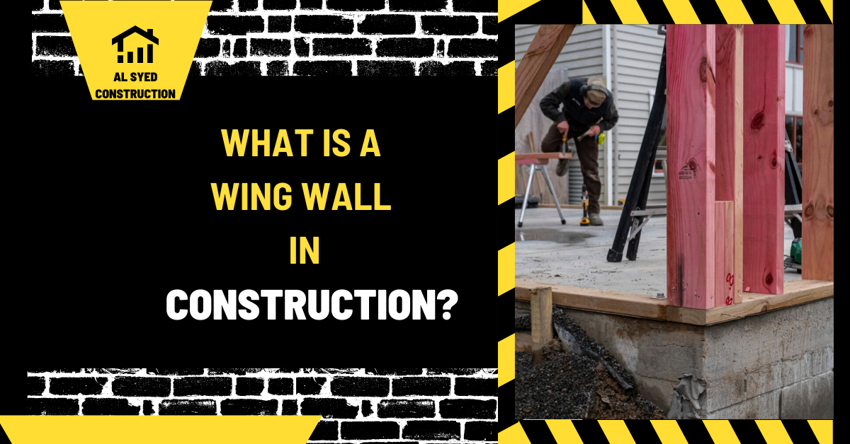
What Is a Wing Wall in Construction?
A wing wall is a retaining wall connected to or placed beside a bridge abutment. It holds back the approach fill at the sides of the bridge and helps shape the transition from the roadway embankment to the bridge opening. The wall can extend parallel to the roadway, flare away from it, or return toward the embankment depending on the site geometry. Its job is related to the abutment, but the wing wall is not the part that normally supports the bridge deck bearings.
That distinction matters. The abutment receives the bridge superstructure’s end reactions and transfers them to the foundation; the wing wall retains soil and helps protect the approach. The two structures interact through backfill, drainage, joints, and sometimes structural connections. This guide explains wing-wall function, common layouts, design considerations, construction checks, and signs that deserve an engineering inspection.
The wing wall’s role at a bridge end
Road approaches are usually built on compacted soil or engineered fill, while the bridge deck is carried by a concrete or masonry support. At the bridge end, the wing wall confines that fill so it does not spill into the waterway, roadway, or open area beside the abutment. It also defines the edges of the approach and can help guide runoff away from vulnerable ground.
The abutment and wing wall often meet at a corner or a designed joint. Depending on the bridge arrangement, the wing wall may be integral with the abutment, attached to it, or structurally separate. A connected wall must be detailed for the forces and movement expected at that connection. A separate wall needs a stable foundation and a joint that allows the movements anticipated by the design. The appearance of a continuous concrete surface does not tell the whole structural story.
Wing walls are common where a bridge crosses a stream, drainage channel, road, or rail line. They can also appear at culverts and retaining transitions. A wing wall’s geometry affects how much soil it retains, where water drains, and whether vehicles or maintenance equipment may approach the wall. Those conditions should be understood as part of the bridge layout, not treated as landscaping details.
Common wing-wall layouts
A straight or parallel wing wall generally follows the roadway direction or runs roughly parallel to the abutment. This can create a compact footprint when space is limited, but it may leave a more abrupt transition between the bridge and the embankment. Designers consider the wall height, backfill profile, drainage route, and the way the wall meets adjacent ground.
A flared or splayed wing wall angles outward from the abutment. It can guide the embankment into a wider approach, help frame the bridge opening, and accommodate the road’s footprint. The angled layout may require more property and a longer wall. Its end condition, slope protection, and drainage need attention so water does not erode the soil around the wall.
A return wing wall turns back toward the roadway or embankment. This can retain a compact fill area or create a defined enclosure beside a bridge. Some bridges use free-standing walls, while others have wing walls that are supported by or tied to the abutment. A short “flying” wall may project from the abutment stem. The exact classification and details vary by agency and structural arrangement, so plans should identify the wall type and connection.
Loads, movement, and drainage
A wing wall must resist the pressure of the soil it retains. The design may also consider surcharge from traffic, barriers, nearby equipment, or other loads near the top of the wall. Groundwater or trapped water can add pressure if drainage is inadequate. The wall and its foundation must be checked for the project’s design conditions, including sliding, overturning, bearing, structural strength, and settlement as applicable.
Water management is a major long-term performance issue. Surface runoff from the roadway or embankment should not be allowed to concentrate behind the wall. Subsurface drainage may be detailed to relieve water pressure, and outlets must discharge where flow will not erode the toe or slope. FHWA bridge guidance emphasizes controlling surface and subsurface water near wing walls and abutments; a drain is useful only if it remains open and has a safe outlet.
Movement can occur as the bridge and approach respond to temperature, shrinkage, soil settlement, and traffic. An integral wall experiences forces through its connection to the abutment. A separate wall may move differently and needs a suitable joint. The design coordinates wall height, reinforcement, foundation conditions, and backfill so that expected movement does not create a damaging gap or trap water. Field crews should not fill or seal a joint with an unapproved material.
How the wall works with the abutment and approach
The abutment carries the end of the bridge and provides the seat or interface for its bearings, while the wing wall supports the soil at the sides. The bridge span and bearing arrangement therefore affect the abutment geometry, and that geometry sets the connection point for the wing walls. A full bridge-building guide can help place these components in the overall structure.
Backfill is not simply dumped behind the wall. It must meet the specification, be placed and compacted in controlled lifts, and avoid displacing the wall or damaging drainage elements. Compaction equipment close to a wall can impose different loads from the eventual soil pressure. The construction sequence and equipment limits should be established by the project documents. If the wall moves, cracks, or leans during backfilling, work should pause for review rather than covering the condition.
The road approach needs a stable transition to the bridge deck. Settlement behind an abutment can produce a bump at the bridge end, while poor drainage can soften the fill or wash it out along the wing wall. Approach slabs, pavement joints, slope protection, and drainage details address different parts of this transition. No single wall element can compensate for a poorly designed approach system.
What designers consider when selecting a layout
The wall arrangement begins with the road alignment and the shape of the approach fill. Designers map property lines, stream or channel boundaries, utilities, slopes, and obstacles. They check whether a flare is needed to retain a broad embankment or whether a parallel wall fits the right-of-way. The bridge skew—the angle between the bridge and the feature it crosses—can make one side longer or more complex than the other.
Hydraulic and geotechnical conditions are also important. A wall beside a waterway may be exposed to flood flow, debris, or scour. The foundation and slope protection must match the site assessment, and the design must avoid directing runoff into unstable ground. The retained soil’s properties and groundwater conditions influence wall pressure and foundation demands. A standard detail is appropriate only when the project conditions fall within its stated limits.
The wall’s visibility and use can affect finish and safety details. Barriers, railings, crash protection, maintenance access, and architectural treatment may be required. The face may need a specified finish, but appearance should not hide a drainage outlet or inspection crack. At a pedestrian bridge, the wall can affect the edge protection and accessible route; at a highway bridge, roadside safety details may govern.
Construction sequence and inspection points
Before excavation, crews locate utilities and verify the approved limits. The foundation area is excavated to the planned lines and elevations; unsuitable material is addressed through the engineer’s direction. Reinforcement, footing geometry, connection dowels, waterstops, and embedded items are checked before concrete is placed. Forms are braced for the planned pour, and any joint between the wall and abutment is built as detailed.
After the footing or base is accepted, the wall stem is formed, reinforced, and placed. Inspectors verify bar size and position, concrete cover, form dimensions, joints, drainage components, and surface outlets. Concrete curing and form removal follow the specification. Backfill begins only when the element has reached the required condition and the approved sequence allows it.
As backfill is placed, the team checks lift thickness, material, moisture, and compaction method according to the project requirements. Drainage layers and geotextiles must be protected from contamination or blockage. Compaction equipment should remain within the specified distance and load limits. The final grading should send runoff to planned drainage features rather than toward the wall. Photographs and inspection records help connect concealed drainage work to the finished bridge.
| Site condition | Wing-wall detail to review |
|---|---|
| Narrow right-of-way | Parallel or compact return geometry and construction access |
| Wide approach embankment | Flared layout, retained soil length, and slope protection |
| Bridge skew | Unequal side lengths, joint alignment, and drainage outlet locations |
| Waterway exposure | Flood flow, scour potential, erosion protection, and foundation conditions |
| High groundwater | Drainage, water pressure, outlet maintenance, and backfill permeability |
Defects, maintenance, and inspection clues
A crack can result from shrinkage, restraint, settlement, impact, or a structural problem; the pattern and movement matter. A narrow stable surface crack is different from a widening crack that passes through the wall or extends into the abutment. Inspectors note crack location, length, width, water staining, rust, offsets, and changes over time. Do not diagnose capacity from a photograph alone.
Look for bulging, tilting, separation at the joint, exposed reinforcement, spalling, settlement of the approach, and erosion at the wall toe or top. Water emerging from an outlet can be expected after rain, but sediment discharge, persistent wet ground, or a blocked outlet may point to a drainage problem. A void or sinkhole behind the wall can mean soil is escaping through a crack or outlet.
Maintenance may include clearing approved drainage outlets, repairing slope protection, replacing joint sealants, and documenting changes. Any repair that alters the wall, drainage, reinforcement, or connection needs review by the bridge owner and qualified engineer. Temporary patching can hide movement or route water into a different part of the structure. Routine inspection is most useful when observations are compared with prior reports and measured against the correct bridge component.
Common questions
Does a wing wall support the bridge deck?
Usually its primary function is to retain approach soil, not to carry the deck’s main bearing reactions. The abutment supports the bridge end. A particular design can connect the wing wall structurally to the abutment, so the project drawings define the actual load path.
Are wing walls always attached to abutments?
No. Some are integral or connected; others are detailed as separate walls with movement joints. The choice depends on the structure, geometry, foundation conditions, and expected movement. Never assume a joint is accidental or fill it without approval.
Why does a wing wall need drainage?
Water trapped behind a retaining wall can increase pressure and saturate backfill. A designed drainage path helps manage water, but its outlet must remain functional and discharge without causing erosion. Drainage details are part of the wall system, not optional accessories.
Can a wing wall be repaired with surface concrete?
Only after the cause and extent of the damage are evaluated. Surface patching may be appropriate for a limited defect, but it will not correct settlement, failed drainage, foundation movement, or a compromised connection. The owner’s engineer should select the repair.
What is the difference between an abutment and a wing wall?
The abutment supports the bridge superstructure at its end and may retain earth behind the bridge seat. Wing walls extend beside it to retain side approach fill and shape the embankment. They work together but have distinct functions.
A reliable way to assess a wing wall
Start with the bridge plans to identify whether the wall is integral, attached, or separate. Then check its retained height, foundation, drainage, backfill sequence, and exposure to water or traffic. During inspection, record changes instead of relying on a single visual impression. A wing wall is a relatively small part of a bridge, but poor drainage or soil movement at that location can damage the approach and threaten the stability of the transition. Design, repair, and acceptance should follow the project documents and the responsible bridge authority’s engineering review.



Leave a Reply
Want to join the discussion?Feel free to contribute!