
What Is an Abutment in Construction?
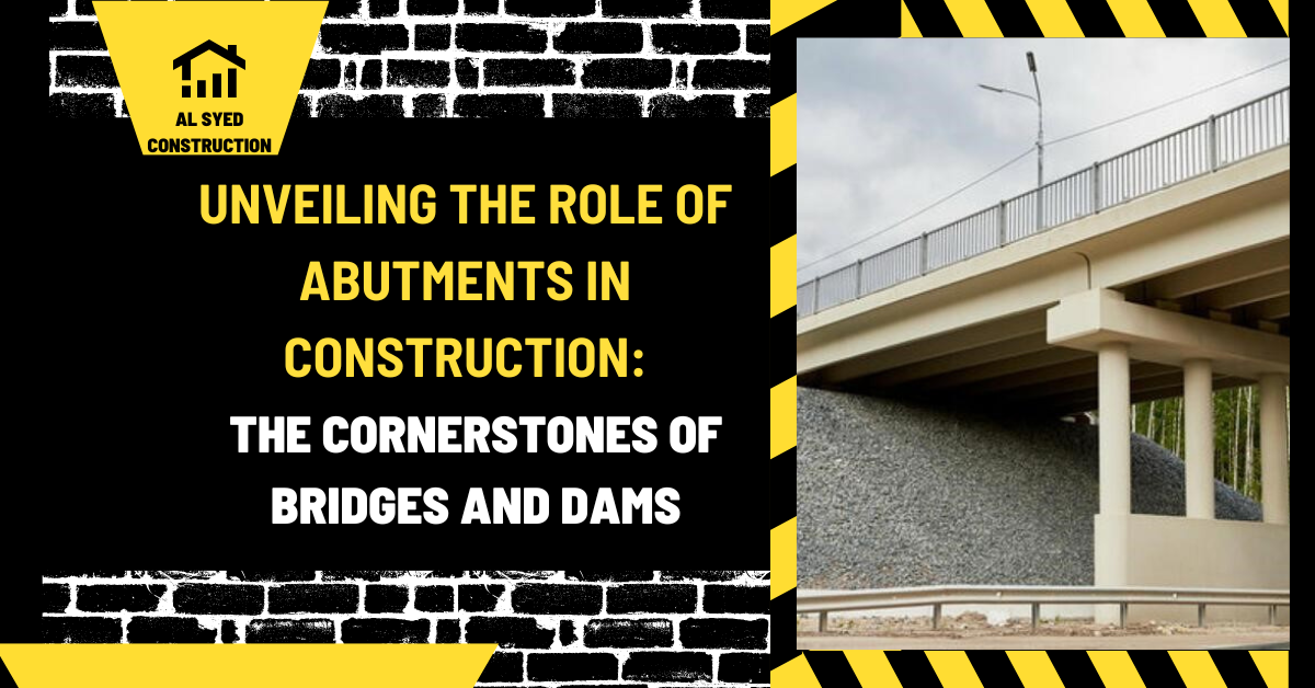
An abutment is the structural support at the end of a bridge. It transfers the bridge superstructure’s reactions into the foundation and often retains the soil of the roadway approach. Depending on the bridge design, an abutment may include a footing or deep foundation, a stem or breastwall, a bridge seat, backwall, bearings, and connections for approach slabs or wing walls. The exact arrangement varies with the span, site, and agency standards.
Abutments do more than hold up the deck. They interact with soil, water, traffic, temperature movement, settlement, and sometimes flood debris or vehicle impacts. A sound design coordinates structural capacity, geotechnical conditions, drainage, bridge bearings, and approach geometry. This guide explains the abutment’s parts, how it differs from a pier, and what to review during design, construction, and inspection.
The abutment’s place in the bridge load path
Traffic and other loads reach the deck, then pass into beams, girders, trusses, arches, or another superstructure. At the end of the bridge, bearings or designed connections transfer reactions into the abutment. The abutment then carries those forces to its foundation and the ground. At the same time, the wall may resist pressure from approach fill behind it. The structure therefore responds to both bridge loads and retained-soil effects.
The superstructure’s span arrangement determines the reactions delivered to the abutment. A simple span, continuous bridge, and movable bridge do not impose identical support conditions. A bridge may need bearing seats that permit rotation or movement, while other details restrain selected directions. The design defines which movements are allowed and how the load is transferred. Bearings should not be adjusted or replaced without checking the project requirements.
Abutments are often located close to waterways, roads, or property boundaries. Their foundation may be exposed to scour, groundwater, frost, weak soils, or nearby excavation. A bridge’s span dimensions help describe support spacing, but the abutment design must also account for local ground conditions and clearance requirements.
Typical abutment components
The footing spreads load to soil or rock for a shallow foundation. Where near-surface material cannot safely support the load, piles, drilled shafts, or another deep-foundation system may transfer it to stronger strata. Foundation selection relies on site investigation and structural demands. It is not chosen only from the bridge’s visible size.
The stem or breastwall rises from the foundation and supports the bridge seat. A backwall may retain the approach material and define the end of the deck. The bearing seat provides a surface and geometry for the bridge bearings. Reinforcement, shear keys, anchors, or other connections may be included as the design requires. Construction joints separate planned placements and need correct preparation and treatment.
Wing walls extend beside the abutment to retain approach fill and shape the embankment. They may be attached, integral, or separated by a movement joint. Drainage elements behind the wall and within the approach are important because water pressure can add demand and water flow can erode soil. The wing-wall guide covers these side walls in more detail.
Abutment types and structural arrangements
A full-height abutment has a wall that retains a substantial depth of approach fill. It can be supported on a spread footing or deep foundation and may include wing walls. Its design must account for bridge reactions and earth pressure, together with surcharge and water conditions relevant to the site.
A stub abutment is shorter and often sits near the top of an embankment. The soil slope or reinforced fill may provide much of the approach transition. This can reduce the wall height, but the project still needs stable fill, drainage, erosion protection, and a designed connection to the bridge. A stub arrangement may be less intrusive in a waterway than a tall wall but still depends on foundation and embankment performance.
Some bridges use integral abutments that connect the superstructure and abutment without conventional expansion bearings at the ends. Thermal movement is accommodated through designed flexibility in the system and surrounding soil. Other arrangements use bearings and joints to manage movement. An integral detail is not simply a rigid connection; it requires analysis of cyclic movement, pile response, soil interaction, and bridge length.
Abutment versus pier
An abutment supports the bridge at an end. A pier supports the bridge at an intermediate location between its ends. Both transfer superstructure forces to foundations, but an abutment often retains approach fill and creates a transition to the roadway, while a pier usually stands within the bridge’s span system. In a waterway, a pier may be exposed to flow and debris; an abutment may be near a bank or floodplain. Site exposure changes the design and inspection emphasis.
Some bridge layouts use only abutments, with a single span between them. Longer crossings may use piers to create multiple spans. Whether adding a pier is appropriate depends on hydraulic clearance, foundation feasibility, construction access, environmental constraints, and whole-life cost. A pier can shorten superstructure spans but introduces additional foundations and inspection locations. The comparison must include construction effects and maintenance, not just member size.
The distinction also helps interpret drawings. If a support is at the end and retains the approach, it is generally an abutment; an interior support between spans is a pier. A specific structure can combine unusual shapes and functions, so the plans and bridge inventory define component names. Do not identify a wall solely from its appearance in a photograph.
Design issues that control performance
Geotechnical investigation defines soil and rock layers, groundwater, settlement potential, lateral resistance, and foundation alternatives. Designers evaluate the bridge reactions together with retained earth pressure, surcharge, seismic demands, and water conditions as required. The wall and foundation must be stable for the applicable load combinations. Calculations and details follow the governing bridge specifications and responsible agency review.
Drainage is critical behind an abutment. Water trapped in backfill can increase pressure, soften the soil, or escape through joints and cracks. Surface grading, underdrains, filter material, outlets, and waterproofing are detailed to suit the structure. FHWA design examples highlight drainage in abutment and wing-wall design because unbalanced water pressure and uncontrolled surface runoff can undermine performance.
Bridge movement is another design driver. Temperature changes, concrete shrinkage, creep, braking forces, settlement, and bearing behavior affect the connection between deck and abutment. Expansion joints may admit water and debris if not maintained. Integral abutments handle movement through a different structural mechanism. The design coordinates the deck, bearings, backwall, approach slab, wing walls, and joints as a system.
Hydraulic and scour analysis matters when the abutment is near a stream. Flow can erode approach fill or undermine the foundation. The project may use riprap or another approved countermeasure, but protection requires inspection and maintenance. A stable-looking wall can still be at risk if the channel changes or scour protection is displaced.
Construction sequence and hold points
Construction begins with survey control, utility checks, traffic or waterway controls, excavation limits, and approved temporary works. The foundation is exposed and evaluated before concrete or deep-foundation work proceeds. Piles or drilled shafts are installed and documented as designed. Unexpected refusal, poor material, or groundwater conditions require a formal engineering review rather than unapproved field changes.
Footing reinforcement, dowels, waterstops, embedded items, and formwork are inspected before placement. The wall stem and bearing seat are built to the specified elevations, line, and dimensions. Concrete placement, curing, form removal, and repair follow the project specification. Bearing areas need particular dimensional accuracy because their elevation and orientation affect load transfer and bridge geometry.
Backfill is placed only after the abutment reaches the required condition and the sequence allows it. Material, compaction, drainage layers, and equipment limits follow the plans. Heavy compaction equipment close to a wall may impose loads that differ from normal service pressure, so the contractor observes specified setback and procedures. The approach slab, pavement, joint, and deck connection are then completed and inspected.
| Component | Primary role | Key interface to inspect |
|---|---|---|
| Foundation | Transfers abutment forces to soil or rock | Bearing material, piles or shafts, settlement |
| Stem or breastwall | Supports bridge seat and may retain fill | Reinforcement, joints, drainage, wall movement |
| Bridge seat | Supports bearing or connection | Elevation, flatness, bearing position |
| Backwall | Retains approach and defines deck end | Joint, approach slab, water management |
| Wing wall | Retains side fill beside the abutment | Connection, drainage outlet, erosion protection |
Inspection clues and common problems
Inspectors look for settlement, rotation, cracking, spalling, exposed reinforcement, bearing displacement, joint leakage, and loss of material around the foundation. A crack’s direction, width, change over time, and relationship to the bearing seat or footing all matter. Water staining and efflorescence can signal leakage, but do not by themselves diagnose the source or structural impact.
Approach distress can be an early clue. A bump, settlement, open pavement joint, void, or erosion channel near the bridge end may indicate movement or loss of backfill. Check whether drainage outlets are open and whether water is being directed toward the wall. At a waterway, compare current conditions with prior inspections for scour, bank migration, debris accumulation, or displaced protection.
Repairs should address the cause. Filling a crack without correcting a drainage or movement problem may conceal the symptom while allowing damage to continue. Bearing replacement, foundation repair, soil improvement, and structural strengthening require the bridge owner’s engineering process. Record measurements, photographs, date, water level, and recent weather so future inspections can assess change rather than relying on memory.
Common questions about abutments
Does every bridge have two abutments?
Most conventional bridges have an abutment at each end, but special structures and complex crossings can have unusual arrangements. Each bridge’s plans identify the terminal supports and how they connect to the approaches.
Does the abutment carry the bridge’s weight?
It carries the reactions delivered at the bridge end and transfers them to its foundation. The amount and direction of force depend on the span arrangement, superstructure, bearings, loads, and support conditions.
Can an abutment be built directly on soil?
Some abutments use shallow footings on suitable soil or rock. Others require piles, drilled shafts, or another foundation system. Site investigation and engineering determine the foundation; there is no universal rule based on bridge size alone.
Why does an abutment need a backwall?
A backwall commonly retains approach material and defines the end of the deck. Its exact function and connection vary by design. The detail must manage soil pressure, drainage, deck movement, and the approach slab connection.
How is an abutment affected by water?
Groundwater can increase pressure behind the wall, while stream flow can erode approach fill or scour a nearby foundation. Drainage, hydraulic design, erosion protection, and ongoing inspection address those risks.
A complete view of the bridge end
An abutment is the bridge’s terminal support and an important transition between structure and roadway. Its reliability depends on the foundation, bearing seat, retaining wall, approach fill, joints, drainage, and construction sequence working together. When reviewing a design or inspection, identify the load path, movement provisions, water routes, and adjacent soil conditions. That system view makes it easier to spot the real cause of a problem and plan a durable repair.



Leave a Reply
Want to join the discussion?Feel free to contribute!