

Maximum Beam Span for Residential Construction: A Practical Guide
There is no single maximum beam span for every house. The distance a beam can safely cross depends on what it supports, the beam material and size, its support and bracing, and the building requirements that apply to the project. A beam carrying only a light roof can have a very different allowable span from one carrying a concrete floor, masonry walls, or several storeys.
To find the maximum span for a particular residential beam, a qualified designer must establish its loads and support conditions and check strength, deflection, connections, and the structure beneath it. A code or manufacturer’s span table is useful only when its assumptions match the actual application.
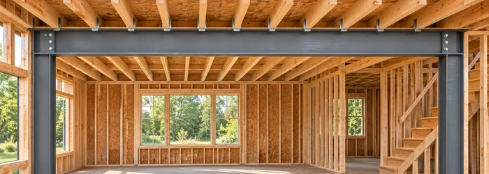
What Is Beam Span in Residential Construction?
A beam is a structural member that carries loads across an opening and transfers them to supports such as walls, columns, or other beams. In a house, it might support floor joists, a roof, a wall above a wide opening, or a reinforced concrete slab.
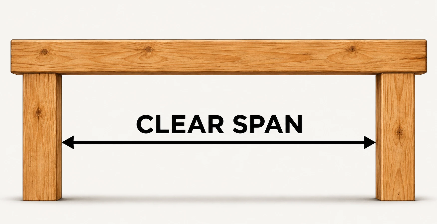
Beam span describes the distance over which the member carries load between supports. A room’s width is not necessarily the beam’s design span: the beam may bear on supports beyond the visible opening, or the support positions may be concealed inside walls.
Clear span is the unobstructed distance between the inside faces of the supports. A table or analysis may use a different definition, such as a distance between support centerlines or another effective span. Always use the definition specified by the applicable method.
Beam, joist, girder, and header: what is the difference?
A joist is typically one of several parallel members supporting a floor or ceiling. A beam may support several joists. A girder is generally a principal beam supporting other framing, while a header commonly spans a door, window, or other wall opening. Usage varies, so identify the member’s job rather than relying on its name alone. A joist span chart cannot automatically be used to size the beam that supports those joists.
How Far Can a Residential Beam Span Without Support?
The answer depends on the complete design. There is no universally safe 10-foot, 20-foot, or other span for every steel, timber, LVL, or reinforced concrete beam. Longer clear openings can be feasible with an appropriate engineered system, but feasibility does not mean a particular beam is adequate for a particular house.
For a proposed opening, provide the designer with the opening dimensions, framing layout, number of storeys, roof and floor construction, expected wall and equipment loads, and the location and condition of supports. The designer can then identify the allowable span for a specified member under those conditions.
An important distinction: a piece of lumber supplied in a certain length is not automatically permitted to span that entire length. Product availability, architectural clear distance, and approved structural span are different things.
What Determines the Maximum Beam Span?
1. Loads and the area supported
Dead loads include the permanent weight of structural members, floors, finishes, roofing, and walls. Live loads generally include people, furniture, and other occupancy-related use. Depending on the site and structure, roof live load, snow, wind, earthquake effects, equipment, or water tanks may also matter.
A beam often receives load from an area of floor or roof, not just from the material directly above its visible width. That assigned area is commonly called its tributary area. A wider tributary area usually means more load on the beam when other conditions remain unchanged.
A masonry wall, another beam framing into the member, or a column above it can add a line load or a concentrated load. These must not be ignored simply because the floor looks ordinary.
2. Material and member properties
Wood span depends on species, grade, condition, moisture exposure, and section. Engineered wood depends on the specific product, grade, ply configuration, orientation, and manufacturer’s instructions. Steel depends on its section, grade, stability, connections, and fire-protection requirements. Reinforced concrete depends on concrete and reinforcement properties, section geometry, detailing, and the way the beam acts with adjoining members.
A member described only as “a 2×12,” “a steel I-beam,” or “a concrete beam” does not contain enough information to determine its allowable span.
3. Depth, stiffness, and deflection
Increasing a beam’s depth can improve its resistance to bending and reduce deflection, but the effect depends on its shape and material. A member may meet a strength requirement yet still bend enough to crack finishes, affect doors, or make a floor feel uncomfortable.
Deflection limits depend on the applicable code, loading, finishes, and design criteria. Some tables use limits expressed as a fraction of span, such as L/360, but the appropriate limit is not universal. Long-term movement, vibration, and cracking may also need attention.
4. Supports, continuity, and bracing
A simply supported beam has a different structural model from a continuous beam, a fixed frame member, or a cantilever. The engineer must establish where and how the beam is supported and whether its compression region has the required lateral restraint.
Support details matter: bearing length, connectors, posts, wall framing, and foundations must resist the forces delivered by the beam. An intermediate post can shorten individual spans, but it also creates a concentrated load that must be supported all the way to the ground.
5. Building rules and site conditions
The governing building code, its adopted edition and local amendments depend on the project location. Wind, snow, seismic exposure, soil, fire requirements, and construction practices can affect the solution. A table published for one country or locality should not be assumed valid for another.
Residential Beam Materials: How Do They Compare?
| Beam material | Typical residential use | Main checks and limitations |
|---|---|---|
| Solid-sawn or built-up timber | Floor beams, small openings, roof support | Species, grade, load, ply connections, bearing, moisture, and code-table assumptions. |
| LVL or other engineered wood | Headers, open-plan floors, roof beams | Exact manufacturer and grade, number of plies, load location, fastening, bearing, and exposure. |
| Structural steel | Wide openings, renovations, support for floors or walls | Section capacity, lateral restraint, connections, fire protection, corrosion, and support reactions. |
| Reinforced concrete | Concrete frames, slabs, and masonry-supported homes | Bending, shear, cracking, deflection, anchorage, reinforcement detailing, construction stages, and foundations. |
Wood and engineered wood beams
Timber is common in light-frame houses because it is readily worked and can be economical where the loads and geometry fit available products. Built-up beams must be assembled using the required fasteners and ply connections; merely placing boards together does not establish that they act as the intended beam.
LVL, glulam, and other engineered wood products are available in different strengths and sizes. Use the specific manufacturer’s current design information for the product, region, and application. A span table for solid lumber should not be substituted for a proprietary LVL table, and one manufacturer’s table should not automatically be applied to another product.
Steel beams
Steel can be useful where a large opening or limited available depth makes another solution difficult. A steel beam must still be checked for strength, stiffness, stability, bearing, connection forces, and its interaction with the surrounding structure. A shallow beam is not automatically sufficient simply because it fits above a ceiling.
Its total cost can include fabrication, delivery, lifting, posts, foundation changes, protection, and finish repair. These items are particularly important when comparing a steel option with engineered wood in an existing house.
Reinforced concrete beams
A reinforced concrete beam works as part of a system that may include slabs, columns, walls, and foundations. Reinforcement size, placement, anchorage, shear reinforcement, concrete strength, cover, and construction sequence all matter. A span-to-depth rule or a beam size copied from another house is not a completed design.
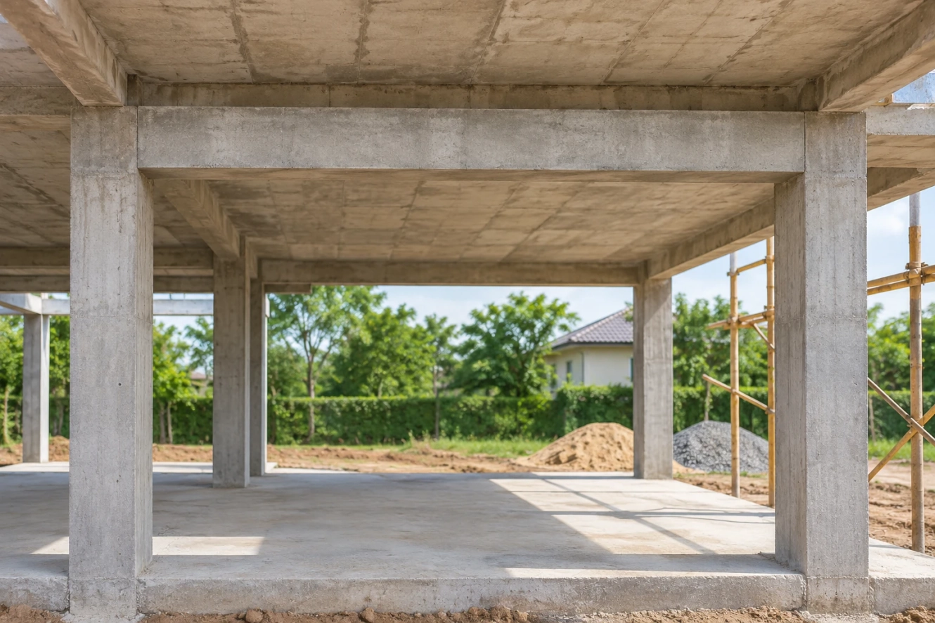
In homes with masonry infill or concrete roofs, the designer should account for the actual materials and support conditions. Local earthquake requirements can affect the complete frame and its detailing; the approved structural drawings govern the work.
How to Read a Beam Span Table
A span table is a set of pre-calculated results for defined conditions. Before reading a number, identify:
- Jurisdiction and edition: Is the table applicable where the home is being built or altered?
- Application: Is it for a floor beam, roof beam, header, joist, or another member?
- Loading and supported width: What floor, roof, wall, snow, and tributary-width assumptions are included?
- Material and configuration: Does the species, grade, product, size, number of plies, and orientation match?
- Support and bracing: Are the number of spans, end bearing, lateral restraint, and connections the same?
- Deflection and other limits: Which serviceability criteria and exceptions apply?
- Footnotes and exclusions: Are concentrated loads, heavy finishes, unusual walls, or other conditions outside the table’s scope?
If the project does not fit a table, that does not necessarily mean it cannot be built. It means the table alone cannot establish the answer; a project-specific design may be required. Local officials or the responsible engineer should confirm the applicable route.
A Simple Tributary-Load Example
Suppose a floor has an assumed uniform area load of 50 pounds per square foot, and a simple framing arrangement assigns a 10-foot tributary width to a beam. Multiplying 50 psf by 10 ft gives an illustrative 500 pounds per linear foot of floor load on that beam.
This is only a unit and load-path example. The assumed load is not a required design load, and the calculation does not select a beam or establish a safe span. It excludes the beam’s own weight, walls, concentrated loads, load combinations, support details, and other project-specific requirements. A continuous joist system or unusual geometry can require a different load distribution.
A complete design then evaluates the beam and the reactions at its supports. The columns, walls, connection hardware, footings, and soil below must be appropriate for those reactions as well.
Common Residential Beam Span Scenarios
Opening a load-bearing wall
An open-plan renovation may replace part of a load-bearing wall with a beam. The beam must account for what the wall carried, which can include floors, roof framing, masonry, or another support above. The remaining wall may also participate in resistance to lateral loads.
Before demolition, a qualified professional should investigate the load path and prepare a design, including temporary support, installation sequence, connections, and support below. A post ending on an existing floor is not necessarily supported by an adequate foundation underneath.
Garage door and exterior openings
A garage header or beam may support a wall, floor, and roof above the opening. An exterior location may also introduce wind and durability requirements. A wide garage opening should not be sized from the door width alone; the tributary loads and wall system must be established.
A floor beam in a new house
For a beam supporting joists on one or both sides, the supported joist lengths and resulting tributary width are key inputs. The designer must also check whether other loads, such as a bathroom finish, partition, or point load from above, are included.
A beam below a concrete roof or water tank
Concrete slabs, masonry, and stored water can introduce substantial loads compared with lightweight roof framing. The tank’s location and support arrangement can create concentrated forces. Confirm the entire roof-to-foundation load path rather than applying a timber roof-beam table to the situation.
What Changes When a Span Gets Longer?
Increasing span can increase bending demand and deflection, even if the load per unit length stays the same. A deeper or different member, more lateral restraint, a different framing arrangement, or an additional support may be considered by the designer.
The choice involves more than material cost. A deeper beam may reduce headroom or conflict with ducts; a heavier beam may require lifting equipment; an extra post can interrupt the floor plan and require a new footing. The best arrangement depends on the structure and the owner’s priorities.
Can an additional column solve the problem?
It can reduce the length of individual spans, but only if it is designed and properly supported. Adding a post changes how forces flow through the building and may require a footing or other foundation work. A post on a slab or timber floor should not be assumed adequate without checking what is beneath it.
Installation and Inspection Considerations
The approved plans and product instructions should show the member, grade, supports, fasteners, bearing, and necessary bracing. For built-up and engineered wood beams, follow the specified ply fastening and hanger details. For steel, verify connection and protection details. For concrete, placement, reinforcement inspection, curing, formwork, and shoring must follow the approved construction plan.
Do not cut, notch, drill, weld, or alter a structural beam unless the proposed modification has been reviewed and approved. A hole for a pipe or an unauthorized reduction in bearing can change the behavior of the member and its connections.
For an existing beam, new or increasing sag, significant cracking, corrosion, crushing at supports, or a shifted post warrants professional assessment. If failure appears imminent, keep people away from the area and follow local emergency procedures.
Common Mistakes When Estimating a Maximum Beam Span
- Treating a room’s width as the only required input.
- Using a joist span table for a main beam or a roof table for a floor beam.
- Ignoring the weight of masonry, finishes, equipment, or the beam itself.
- Assuming all engineered wood products have identical properties.
- Copying a beam size from a similar-looking house.
- Checking beam strength while overlooking deflection, stability, bearing, or connection details.
- Adding a support without checking the floor, footing, and soil beneath it.
- Using a calculator result without reviewing its assumptions and the governing code.
Questions to Ask Your Structural Engineer or Contractor
- What is the measured clear opening, and which span definition does the design use?
- Which floors, roof areas, walls, and concentrated loads does the beam carry?
- What material, product grade, dimensions, and support arrangement are specified?
- What are the expected support reactions, and are the existing footings suitable?
- What deflection, bracing, connection, fire, and durability requirements apply?
- Is temporary shoring needed, and who approves its removal?
- What permits, inspections, and documentation are required locally?
Frequently Asked Questions
What is the maximum beam span for a house?
There is no universal number. It is the maximum allowed for a particular member under its actual loads, supports, serviceability requirements, and governing rules.
Can a beam span 20 feet in a residential building?
A 20-foot opening may be achievable with an appropriate engineered system, but the span alone cannot establish the required material or size. The full load path and project requirements must be checked.
How far can an LVL beam span without a post?
It depends on the specific LVL product, grade, number of plies, depth, supported loads, restraint, bearing, and applicable design criteria. Use the manufacturer’s relevant tables or a project-specific design; do not assume that the manufactured length is an allowable span.
How far can a concrete beam span between columns?
There is no fixed limit that applies to every concrete frame. The slab, wall and other loads, beam section and reinforcement, support conditions, deflection, earthquake requirements, and construction details all affect the answer.
Is a deeper beam always the right solution?
Not necessarily. More depth can improve stiffness and capacity, but headroom, connections, support reactions, cost, and other design checks still matter. The beam must be assessed as part of the whole structure.
Do all houses use the same beam span table?
No. Tables are specific to a code or product and a set of assumptions. A table intended for one material, load, or jurisdiction may not apply to another.
Conclusion
The maximum beam span for residential construction is a project-specific result, not a fixed distance for every home. Start with the actual opening, loads, material, supports, and local requirements, then verify strength, deflection, connections, and the load path down to the foundation. With that information, a qualified designer can determine whether a proposed opening is feasible and specify the right system for the house.





Leave a Reply
Want to join the discussion?Feel free to contribute!