
Data Center Electrical Infrastructure: Complete Guide
Data center electrical infrastructure is the network of equipment that receives utility electricity, transforms it to usable voltages, protects electrical circuits, provides backup power, and distributes electricity to servers and other critical equipment.
A modern data center may contain thousands of servers operating continuously. AI facilities can further increase the challenge by concentrating large electrical loads into high-density GPU racks.
Supplying these systems reliably requires much more than connecting servers to the utility grid.
A typical electrical path may include:
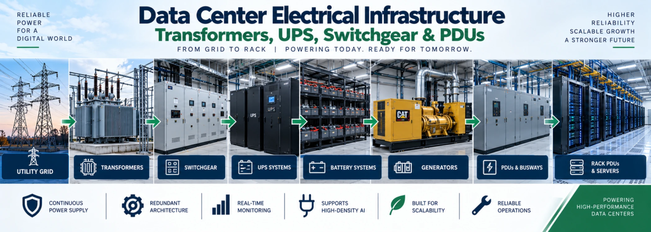
Utility Grid → Substation → Transformer → Switchgear → UPS → Distribution Equipment → Busway/PDU → Rack PDU → Server
Backup generators, batteries, automatic controls, protection systems, grounding, monitoring, and redundant distribution paths can also form part of the electrical architecture.
This guide explains the major components of data center electrical infrastructure, what each one does, how electricity reaches server racks, and how redundancy and backup systems improve reliability.
Why Electrical Infrastructure Is Critical in a Data Center
IT equipment cannot operate without a continuous and correctly controlled electrical supply.
An interruption can affect:
- Servers
- Storage
- Network equipment
- Cooling systems
- Security systems
- Monitoring
- Business applications
- AI computing clusters
Data centers therefore use multiple layers of electrical equipment between the utility and IT load.
These layers perform different functions.
For example:
- Transformers change voltage.
- Switchgear controls and protects circuits.
- UPS systems bridge interruptions and condition power.
- Generators provide longer-duration backup.
- PDUs distribute power closer to IT equipment.
- Rack PDUs deliver electricity to individual servers.
Understanding these components makes the overall electrical architecture much easier to follow.
Data Center Electrical Infrastructure at a Glance
| Component | Primary Function |
|---|---|
| Utility Service | Supplies electricity to the facility |
| Substation | Receives and distributes high-capacity electrical service |
| Transformer | Changes voltage |
| Switchgear | Switching, isolation and electrical protection |
| UPS | Provides short-term uninterrupted power |
| Battery System | Stores energy for UPS operation |
| Generator | Provides backup power during utility outages |
| ATS/Transfer Equipment | Transfers loads between power sources |
| PDU | Distributes electrical power to downstream loads |
| Busway | Provides scalable power distribution |
| Rack PDU | Supplies individual IT devices within a rack |
| Grounding/Bonding | Provides reference and fault-current paths |
| Monitoring | Tracks electrical performance and equipment condition |
How Power Flows Through a Data Center
Although every facility is different, electricity generally moves from higher-voltage infrastructure toward progressively smaller loads.
A simplified example is:
Utility → Transformer → Main Switchgear → UPS → Distribution → Rack → Server
At each stage, the system may:
- Change voltage
- Protect circuits
- Isolate equipment
- Provide redundancy
- Monitor power
- Distribute load
Large campuses may contain several power trains instead of one central electrical path.
Each power train can serve a particular portion of the facility.
This modular approach can make expansion and redundancy easier to manage.
1. Utility Power Supply
The electrical system begins with the utility connection.
Large data centers may require substantial utility capacity, particularly when supporting AI computing.
Before construction, project teams need to understand:
- Available MW
- Service voltage
- Utility reliability
- Interconnection schedule
- Substation requirements
- Transmission constraints
- Future capacity
- Redundant utility options
The amount of power required depends heavily on IT load and rack density.
Those calculations belong to the power-planning stage and are covered separately here:
AI data center power requirements2. Data Center Substations
A substation forms an important interface between the utility grid and the facility electrical distribution system.
Depending on the project, the substation may contain:
- Transformers
- Switchgear
- Protection equipment
- Circuit breakers
- Metering
- Control systems
- Bus structures
Large campuses may require dedicated substations.
Substation design depends on:
- Incoming utility voltage
- Facility MW
- Redundancy strategy
- Expansion plans
- Utility requirements
- Site layout
Substations also require significant physical space and should therefore be considered during early site planning.
3. Transformers
A transformer changes electrical voltage from one level to another.
Utility electricity may arrive at a voltage unsuitable for direct use by downstream data center equipment.
Transformers step that voltage down through the electrical distribution system.
A simplified example could look like:
Utility Voltage → Medium Voltage → Lower Distribution Voltage → IT Equipment
Actual voltages depend on the facility and regional electrical standards.
Why Data Centers Need Transformers
Transformers allow electrical power to be distributed efficiently while supplying equipment at the voltage it requires.
They may serve:
- Main facility distribution
- UPS systems
- Mechanical equipment
- IT distribution
- Auxiliary loads
Large data centers can contain multiple transformers so different power blocks or electrical paths can operate independently.
Transformer Redundancy
If reliability requirements call for additional capacity, transformer configurations may be designed so that the loss of one unit does not necessarily remove all available power from the intended load.
The appropriate arrangement depends on the overall redundancy architecture.
Additional transformers, however, require:
- More space
- More switchgear
- More cabling
- Additional protection
- Higher capital investment
Redundancy therefore must be designed as part of the complete electrical system rather than added to individual components without coordination.
4. Switchgear
Switchgear controls, isolates, and protects electrical circuits.
It can contain components such as:
- Circuit breakers
- Disconnect devices
- Protective relays
- Busbars
- Metering
- Controls
Switchgear allows electrical sections to be safely disconnected for faults, maintenance, or operating changes.
What Does Data Center Switchgear Do?
Its major functions can include:
Protection
Electrical faults must be detected and isolated.
Switching
Power paths may need to be opened or closed during normal operation or maintenance.
Isolation
Equipment can be separated from energized systems so work can be performed safely under applicable procedures.
Monitoring
Modern switchgear can provide data on:
- Voltage
- Current
- Power
- Breaker status
- Alarms
- Electrical conditions
Switchgear is therefore both a protection system and a major control point in the electrical distribution network.
Medium-Voltage vs. Low-Voltage Switchgear
Data centers can use switchgear at different voltage levels.
Medium-Voltage Switchgear
This can be used closer to the utility service, substations, large transformers, or major electrical distribution.
Low-Voltage Switchgear
This can distribute electricity to downstream equipment at lower voltages.
The exact architecture depends on:
- Facility scale
- Utility voltage
- IT capacity
- Equipment selection
- Electrical design
- Applicable standards
Large AI campuses can make medium-voltage distribution increasingly important because very large amounts of power need to move through the facility efficiently.
5. UPS Systems
A Uninterruptible Power Supply (UPS) provides temporary power when the normal electrical source is interrupted.
The key word is uninterruptible.
Generators require time to detect a utility failure, start, stabilize, and accept load.
IT equipment cannot necessarily wait through that interruption.
The UPS bridges the gap.
A simplified sequence is:
Utility Fails → UPS Immediately Supports Critical Load → Generator Starts → Generator Accepts Load
When utility service returns and the system transitions back to normal operation, the UPS architecture helps maintain continuity according to the facility design.
What Does a UPS Do in a Data Center?
Depending on design, a UPS can:
- Support critical IT loads
- Bridge utility interruptions
- Support transfer to generators
- Condition incoming power
- Help stabilize electrical supply
- Protect sensitive IT equipment
UPS capacity must be coordinated with the intended critical load.
Installing a large amount of IT capacity without sufficient UPS capacity would create a mismatch in the power chain.
UPS Batteries
Many UPS systems use batteries as stored energy.
During normal conditions, the UPS keeps the batteries ready.
If incoming power fails, stored energy supports the connected critical load.
Battery runtime depends on factors such as:
- Battery capacity
- Connected load
- Battery chemistry
- System configuration
- Battery condition
- Temperature
The objective is not necessarily to operate the entire data center on batteries for hours.
In many architectures, batteries provide enough time for generators or another backup source to take over.
Battery Technologies
Different data centers may use different battery technologies.
Examples include:
- Valve-regulated lead-acid batteries
- Lithium-ion batteries
Technology selection can depend on:
- Space
- Weight
- Expected life
- Maintenance
- Temperature
- Safety
- Cost
- Owner standards
Battery systems also require appropriate monitoring, fire protection, ventilation or environmental controls where applicable, and maintenance procedures.
6. Backup Generators
Generators provide an alternate electrical source when utility power is unavailable.
A simplified sequence is:
Normal Operation: Utility → Data Center
Utility Failure: UPS → Critical Load
Backup Operation: Generator → Electrical Distribution → Critical Load
Large data centers can have multiple generators.
Generator systems may include:
- Engine-generator sets
- Fuel storage
- Day tanks
- Fuel piping
- Pumps
- Exhaust systems
- Starting systems
- Controls
- Switchgear
Generator capacity must also account for the facility loads that need to remain operational during an outage.
This can include more than IT equipment.
Cooling systems may need to continue operating because servers continue generating heat.
Generator Redundancy
Generator systems may be designed with redundant capacity.
For example, an architecture may include additional generator capacity beyond the minimum needed to support the intended critical load.
However, redundancy should always be considered at system level.
Having redundant generators provides limited value if another single point of failure remains elsewhere in the electrical path.
7. Automatic Transfer Equipment
Electrical systems need a controlled method of moving loads between normal and emergency power sources.
An Automatic Transfer Switch (ATS) can detect the condition of power sources and transfer connected loads according to its control logic.
A simplified sequence may be:
- Utility power fails.
- UPS supports critical IT equipment.
- Generator receives a start signal.
- Generator reaches acceptable operating conditions.
- Transfer equipment connects the appropriate load to generator power.
- Utility service later returns.
- The system transitions back according to its operating sequence.
Actual data center architectures can use more complex switchgear and control schemes than a single ATS arrangement.
8. Power Distribution Units (PDUs)
A Power Distribution Unit (PDU) distributes electrical power to downstream IT loads.
Depending on architecture, a PDU may:
- Receive upstream power
- Transform voltage where applicable
- Provide circuit protection
- Distribute branch circuits
- Monitor electrical load
Traditional data centers often use floor-mounted PDUs serving groups of racks.
Modern facilities can also use busway-based distribution.
9. Busway Systems
A busway uses enclosed conductive busbars to distribute electricity along a defined path.
In data halls, overhead busway can provide flexible rack power distribution.
Tap-off units can connect individual racks or groups of racks to the busway.
Potential advantages include:
- Flexible rack connections
- Reduced cable congestion
- Easier expansion
- Modular distribution
- Overhead installation
- Load monitoring options
Busway can be particularly useful when rack layouts or power densities may change over time.
Busway vs. Traditional Cable Distribution
Traditional electrical distribution may use dedicated cables from panels or PDUs to racks.
Busway provides a common distribution path with connection points along its length.
| Factor | Cable Distribution | Busway Distribution |
|---|---|---|
| Power Path | Individual cable runs | Common busbar system |
| Rack Changes | May require new cable work | Tap-off locations can add flexibility |
| Overhead Installation | Possible | Common |
| Scalability | Depends on design | Often highly modular |
| Cable Quantity | Potentially substantial | Can reduce long branch cable runs |
| Monitoring | Depends on equipment | Often available at tap-off points |
Neither approach is universally correct.
Selection depends on facility layout, electrical capacity, rack density, flexibility, and owner standards.
10. Rack PDUs
A rack PDU, sometimes called an rPDU, distributes electricity inside an individual server rack.
It connects upstream rack power to devices such as:
- Servers
- Network switches
- Storage equipment
- AI accelerators
Rack PDUs may range from basic distribution strips to intelligent units capable of detailed monitoring.
Intelligent Rack PDUs
Advanced rack PDUs can monitor:
- Voltage
- Current
- Power
- Energy
- Circuit loading
- Outlet-level conditions
This information helps operators understand actual rack power consumption.
For high-density AI racks, rack-level monitoring becomes especially useful because power loads can be substantial.
A and B Power Feeds
Critical IT equipment may be designed with dual power supplies.
One server power supply can connect to A power, while another connects to B power.
A simplified arrangement is:
Power Path A → Rack PDU A → Server PSU A
Power Path B → Rack PDU B → Server PSU B
If one electrical path becomes unavailable, dual-corded equipment may continue operating from the other path, depending on system design and available capacity.
This is a fundamental concept in redundant data center electrical architecture.
Understanding N, N+1 and 2N
Electrical redundancy is commonly described using terms such as:
- N
- N+1
- 2N
N
N represents the capacity required to support the intended load.
If four units are required to support the load, those four units collectively represent N.
N+1
N+1 adds one additional unit beyond the required capacity.
If four units are required:
4 required + 1 additional = N+1
2N
2N generally represents two full-capacity systems or paths, depending on the architecture.
This can provide a higher level of separation but also increases:
- Equipment quantity
- Building space
- Cabling
- Controls
- Maintenance
- Construction cost
Redundancy should be evaluated across the entire electrical path.
Avoiding Single Points of Failure
A redundant electrical system is only as resilient as its weakest critical point.
Potential single points of failure can occur in:
- Switchgear
- Transformers
- Control systems
- Distribution
- Fuel systems
- Cooling power
- Cable routes
Design teams therefore evaluate the complete path from utility source to server.
A system can contain redundant UPS units and generators while still having a vulnerable common distribution component.
This is why integrated electrical architecture matters more than simply counting redundant pieces of equipment.
Electrical Capacity and Rack Density
Higher rack density increases the amount of power that must be delivered through a smaller physical area.
For example, compare two hypothetical racks:
Rack A = 15 kW
Rack B = 100 kW
Rack B requires much greater electrical distribution capacity within approximately the same rack footprint.
This can affect:
- Busway ratings
- Rack PDU capacity
- Cable sizing
- Circuit quantity
- Connectors
- Protection
- Cooling
- Monitoring
Detailed rack-density and MW calculations are covered separately in:
AI data center power requirements and rack densityElectrical Infrastructure for AI Data Centers
AI data centers can create several electrical challenges.
High Rack Density
GPU clusters can concentrate large loads into individual racks.
Large Campus Loads
Multiple high-density data halls can create substantial total MW requirements.
Rapid Load Growth
Infrastructure may need to accommodate new generations of computing hardware.
Cooling Power
High-density computing creates heat that must be removed, adding supporting electrical loads.
Expansion
Future power blocks may need additional transformers, switchgear, UPS systems, generators, and distribution.
AI infrastructure should therefore be designed around realistic equipment loads rather than assuming that all data centers have similar electrical requirements.
Power Infrastructure and Cooling
Electrical and cooling systems are tightly connected.
Servers consume electricity and generate heat.
Cooling systems then consume additional electricity to remove that heat.
Electrical infrastructure may therefore need to support:
- Chillers
- Pumps
- Cooling towers
- Dry coolers
- Air handlers
- CDUs
- Controls
For detailed thermal infrastructure coverage, see:
AI data center cooling systemsGrounding and Bonding
Grounding and bonding are fundamental electrical safety and performance considerations.
A coordinated system can include:
- Equipment grounding conductors
- Grounding electrodes
- Bonding conductors
- Ground buses
- Connections between metallic systems
Proper grounding provides defined fault-current paths and supports protective-device operation.
Data centers contain large amounts of interconnected electrical and electronic equipment, making coordinated grounding particularly important.
Grounding design must follow applicable electrical codes and engineering requirements.
Electrical Protection
Electrical faults must be detected and isolated appropriately.
Protection systems may include:
- Circuit breakers
- Fuses
- Protective relays
- Ground-fault protection
- Differential protection
- Overcurrent protection
Protection settings must be coordinated.
The goal is generally to isolate the faulted portion while avoiding unnecessary interruption to healthy sections of the electrical system.
This requires engineering studies rather than simply installing breakers of appropriate current ratings.
Selective Coordination
Selective coordination refers to coordinating protective devices so the device closest to a fault operates appropriately without unnecessarily opening upstream devices.
Consider a fault on one downstream circuit.
Ideally, the protective device serving that circuit isolates the fault while other unaffected circuits continue operating, where the design and applicable requirements allow.
This concept is particularly important in critical facilities where unnecessary upstream trips can interrupt substantial IT capacity.
Electrical Monitoring
Modern data centers monitor electrical systems continuously.
Measurements may include:
- Voltage
- Current
- Frequency
- Real power
- Apparent power
- Energy
- Power factor
- Breaker status
- UPS status
- Battery condition
- Generator status
- Rack consumption
Monitoring can occur at multiple levels:
Utility → Switchgear → UPS → PDU/Busway → Rack
This creates visibility into how electrical capacity is actually being used.
Capacity Management
Electrical monitoring also supports capacity planning.
Operators need to know:
- How much capacity is installed?
- How much is currently used?
- How much remains?
- Is the load balanced?
- Are individual circuits approaching limits?
- Can additional racks be installed?
A data hall can have unused physical floor space but insufficient electrical capacity for additional high-density racks.
Capacity therefore must be evaluated electrically as well as physically.
Power Quality
Sensitive IT equipment depends on power that remains within acceptable electrical conditions.
Power-quality issues can include:
- Voltage variations
- Harmonics
- Transients
- Frequency deviations
- Unbalanced loads
Transformers, UPS systems, filters, protection, grounding, and appropriate distribution design all contribute to managing power quality.
The required strategy depends on the actual electrical architecture and equipment.
Electrical Rooms and Building Layout
Electrical equipment requires substantial building space.
Facilities may include:
- Transformer areas
- Switchgear rooms
- UPS rooms
- Battery rooms
- Generator yards
- Electrical galleries
- PDU areas
Designers must consider:
- Equipment dimensions
- Required clearances
- Maintenance access
- Replacement paths
- Ventilation
- Fire separation
- Structural loading
- Cable routing
Equipment should not merely fit during initial installation.
There should also be a realistic strategy for maintaining or replacing it later.
Electrical Equipment Foundations and Structural Loads
Transformers, UPS systems, batteries, generators, and switchgear can impose significant loads.
Structural engineers may need to design:
- Equipment pads
- Housekeeping pads
- Foundations
- Support steel
- Floor reinforcement
For detailed structural load considerations inside data halls, see:
data center floor loading requirementsElectrical Equipment and Construction Materials
Electrical rooms and outdoor equipment areas also interact with the building’s structural and enclosure systems.
Material selection can affect:
- Fire resistance
- Equipment support
- Durability
- Weather protection
- Security
For dedicated structural-system coverage, see:
data center construction materialsElectrical Infrastructure and Construction Cost
Electrical systems can represent a major portion of data center development investment.
Cost can be influenced by:
- Utility infrastructure
- Transformers
- Switchgear
- UPS capacity
- Batteries
- Generators
- Busway
- Redundancy
- Electrical rooms
- Monitoring
- Installation labor
Higher redundancy and greater MW capacity generally require more infrastructure.
Detailed commercial analysis belongs to our dedicated guide:
data center construction costPlanning Electrical Infrastructure During Construction
Electrical installation must be coordinated with the overall construction sequence.
Large equipment may need to enter the building before walls or other systems block access.
Typical considerations include:
- Equipment delivery
- Crane access
- Rigging
- Equipment pads
- Room completion
- Cable tray installation
- Busway installation
- Terminations
- Controls
- Energization
- Testing
Long-lead electrical equipment can also influence the project schedule.
Transformers and switchgear, for example, may need to be procured well before the building is ready to receive them.
For the full sequence, see:
data center construction processElectrical Testing and Commissioning
Electrical equipment should be tested before operational handover.
Testing can include:
- Visual inspection
- Mechanical inspection
- Cable testing
- Grounding checks
- Breaker testing
- Relay testing
- Transformer testing
- UPS testing
- Battery testing
- Generator testing
- Transfer testing
- Control verification
The exact tests depend on equipment and project requirements.
Integrated Systems Testing
Individual equipment can work correctly while the complete system still contains integration problems.
Integrated testing evaluates how systems respond together.
For example, a simulated utility outage may test whether:
- Utility power is removed.
- UPS systems support the critical load.
- Generators start.
- Generator voltage and frequency stabilize.
- Transfer occurs correctly.
- Cooling remains available.
- Monitoring detects the event.
- Alarms operate correctly.
This type of testing is essential because data center reliability depends on coordinated system behavior.
Maintenance Bypass
Critical equipment eventually requires maintenance.
Electrical architecture should therefore consider how maintenance can occur without unnecessary interruption.
UPS systems, for example, may include bypass arrangements that allow power to continue flowing while portions of the UPS system are serviced, depending on the design.
Maintenance planning can also influence:
- Switchgear configuration
- Distribution paths
- Redundancy
- Isolation points
- Equipment access
A facility that can survive a component failure but cannot safely maintain that component may still face operational limitations.
Future Expansion
Data center electrical infrastructure should consider reasonable future growth.
Expansion planning may include:
- Spare substation capacity
- Future transformers
- Switchgear expansion sections
- Additional UPS modules
- Generator positions
- Spare busway capacity
- Additional electrical rooms
- Future utility connections
Not every project should install all future equipment immediately.
However, reserving space and connection points can make future expansion significantly easier.
Example Data Center Electrical Power Path
Consider a simplified hypothetical facility.
The electrical path could be:
Utility Service
↓
Main Transformer
↓
Medium/Low-Voltage Switchgear
↓
UPS System
↓
Distribution Switchboard/PDU
↓
Overhead Busway
↓
Rack PDU
↓
Dual-Power-Supply Server
A redundant facility could provide a second independent path:
Path A → Server PSU A
Path B → Server PSU B
The actual design may be considerably more complex, but this example demonstrates how multiple electrical layers connect the utility to the IT hardware.
Data Center Electrical Infrastructure Checklist
Utility and Site
- Confirm available utility capacity
- Confirm service voltage
- Review utility interconnection
- Determine future MW requirements
- Reserve substation space
- Coordinate utility schedule
Transformers
- Determine transformer capacity
- Establish redundancy strategy
- Confirm voltage ratios
- Provide maintenance access
- Coordinate foundations
- Coordinate protection
Switchgear
- Confirm ratings
- Coordinate breakers
- Complete protection studies
- Review selective coordination
- Provide maintenance clearances
- Integrate monitoring
UPS and Batteries
- Define critical load
- Determine UPS capacity
- Establish redundancy
- Select battery technology
- Determine required runtime
- Provide monitoring
- Coordinate safety requirements
Generators
- Determine backup load
- Establish generator capacity
- Define redundancy
- Design fuel system
- Coordinate exhaust
- Provide controls
- Plan load testing
Distribution
- Select cable or busway strategy
- Size downstream distribution
- Coordinate rack feeds
- Provide A/B paths where required
- Monitor circuit loading
- Reserve expansion capacity
Grounding and Protection
- Design grounding system
- Bond metallic systems
- Complete protection studies
- Coordinate protective devices
- Verify fault-current ratings
Commissioning
- Inspect equipment
- Test transformers
- Test switchgear
- Test UPS
- Test batteries
- Test generators
- Test transfer sequences
- Test monitoring
- Perform integrated system testing
- Resolve and retest deficiencies
Common Data Center Electrical Design Mistakes
Treating Utility Capacity as an Afterthought
A facility cannot operate at its intended scale if the required power cannot reach the site.
Designing Only for Current Rack Density
AI hardware can increase rack-level power requirements substantially.
Adding Redundancy Component by Component
True resilience requires evaluating the entire electrical path.
Ignoring Cooling During Backup Power Design
IT equipment continues generating heat during outages, so critical cooling loads may also require backup power.
Underestimating Equipment Space
Transformers, switchgear, UPS systems, batteries, and generators require large spaces and maintenance clearances.
Ignoring Replacement Paths
Large equipment eventually needs maintenance or replacement.
Leaving Commissioning Until the End
Testing should be planned throughout design and construction rather than treated as a final-day activity.
Frequently Asked Questions
What is data center electrical infrastructure?
Data center electrical infrastructure is the complete system used to receive, transform, protect, back up, and distribute electricity from the utility connection to IT equipment and supporting facility systems.
What electrical equipment is used in a data center?
Common equipment includes substations, transformers, switchgear, UPS systems, batteries, generators, transfer equipment, PDUs, busways, rack PDUs, grounding systems, protection equipment, and monitoring systems.
What does a transformer do in a data center?
A transformer changes electrical voltage so power can be efficiently distributed and supplied at the voltage required by downstream equipment.
What is switchgear used for?
Switchgear controls, isolates, and protects electrical circuits. It can contain circuit breakers, protective relays, busbars, metering, and control systems.
Why does a data center need a UPS?
A UPS provides immediate temporary power to critical loads when the normal power source is interrupted. It can bridge the time required for generators or another source to take over.
Why are generators needed if a data center has a UPS?
UPS batteries generally provide temporary stored energy. Generators can provide longer-duration backup power when the utility outage continues.
What is a PDU in a data center?
A Power Distribution Unit distributes electrical power to downstream IT loads. Depending on its design, it may also provide transformation, circuit protection, and monitoring.
What is a rack PDU?
A rack PDU distributes electricity to servers and other equipment inside an individual IT rack.
What is A/B power in a data center?
A/B power uses separate electrical paths to supply dual-corded IT equipment. One server power supply can connect to Path A and the other to Path B, improving resilience when designed correctly.
What does N+1 mean?
N represents the capacity required for the intended load. N+1 adds one additional capacity unit beyond that requirement.
What does 2N mean?
2N generally refers to two full-capacity systems or electrical paths in the relevant architecture. The exact implementation depends on facility design.
Why is electrical infrastructure important for AI data centers?
AI systems can create high rack densities and large facility loads. Electrical infrastructure must deliver this power reliably while supporting backup, cooling, monitoring, and future expansion.
Final Thoughts
Data center electrical infrastructure connects the utility grid to every server operating inside the facility.
The complete power chain may include:
Utility → Substation → Transformer → Switchgear → UPS → Distribution → Busway/PDU → Rack PDU → Server
Generators and batteries provide backup capability, while redundant A/B paths can help maintain power during equipment failures or maintenance events.
The key principle is that these components cannot be designed independently.
Transformer capacity must match downstream requirements. Switchgear must protect the system. UPS capacity must support the intended critical load. Generators must support the required emergency loads. Distribution must handle rack density, and every critical power path must be coordinated with cooling and monitoring.
For modern AI facilities, this coordination becomes even more important as rack densities and total MW requirements increase.
A successful electrical design therefore begins with realistic IT requirements and follows the complete power path from the utility connection all the way to the individual server—while also planning for redundancy, maintenance, testing, and future growth.


